news information
Causes, Hazards, and Emergency Plans for Data Center Fires
  I. Overview  The greatest enemy of a data center is dust, and more critically, data center fires are closely related to it. Once a fire occurs in the data center, the losses can range from hundreds of thousands to tens of millions.  II. Causes of Data Center Fires  1. UPS battery fire: When a battery catches fire, smoke quickly spreads throughout the data center (strictly speaking, UPS batteries should not be stored in the same room as data center equipment, but many organizations place them together due to budget and space constraints). Even if they are not in the same room, the smoke will quickly spread to the data center through connected pathways.  2. Overloaded circuits: When the equipment in the data center cannot meet user demands, adding more equipment to the data center is easy, but the load capacity of the cables is not so easily upgraded. This results in overloaded cables, overheating, and potential fires.  3. Dust accumulation on equipment without timely cleaning: Due to prolonged equipment operation and harsh environments, dust and grease accumulate. If not cleaned promptly, this can lead to short circuits, high-temperature alarms, and fires.  4. Old equipment not replaced or cleaned in time: Especially for cables operating under high loads for extended periods. If cables are not replaced or cleaned in time, the insulation layer may melt due to high temperatures, leading to fires.  III. Fire Emergency Plans  1. Quickly cut off the power supply to the data center.  2. Trigger the fire alarm.  3. Activate the data center fire suppression system (if not in automatic mode).  4. Before the arrival of firefighters, ensure safety and attempt to extinguish the fire if possible. All unrelated personnel should evacuate immediately.  5. Be cautious when using water to extinguish equipment fires; foam extinguishers are preferred.  IV. Post-Fire Equipment Handling and Recovery  After a fire, the most challenging issue is restoring the operation of data center equipment. Before restarting equipment, it is best to perform a thorough cleaning (for equipment extinguished with water, initiate recovery mechanisms immediately. Water entering the equipment can corrode internal components if not addressed promptly, causing greater losses. Therefore, water should be removed quickly). After cleaning, it is best to run the equipment in a new data center to avoid secondary contamination from the old site. It is also recommended to use gas-based fire suppression systems in data centers to minimize economic losses compared to water-based systems. The recovery rate of equipment after gas-based suppression is higher than with water-based suppression. Post-fire recovery procedures include cleaning the data center and equipment, removing dust, removing water and moisture, and eliminating static electricity.  V. Prevention First: Keep the Data Center and Equipment Clean  Modern data centers can be considered the core value area of an organization. Waiting for accidents to happen before addressing them can lead to significant losses, often with unimaginable consequences. Therefore, it is essential to identify the causes of fire accidents and implement preventive measures. Strictly follow data center equipment management regulations, perform regular cleaning and maintenance, and always keep the data center and equipment clean and tidy to reduce fire risks. 
2022-04-11
DC System Maintenance
 I. DC System Maintenance1) Regularly clean the internal dust of high-frequency switching power modules;2) Regularly clean the dust inside the DC panel;3) Perform a discharge test with actual load on the battery once a year. The discharge current should remain stable, discharging about 30% of the rated capacity (discharge at 0.1C for 3 hours). Measure the voltage of individual cells, battery groups, discharge current, and temperature every hour during discharge. After discharge, perform equalizing charging and then switch to floating charging. 4) Measure the voltage of individual battery cells and terminal voltage once a month, check for abnormal deformation or overheating, and maintain complete operation records.5) Check the connection wires once a year for firmness, corrosion, or looseness. Tighten them to the specified torque, and replace corroded wires promptly;6) Do not arbitrarily add or remove individual battery loads within the battery group, as this will cause imbalance in individual battery capacities and uneven charging, reducing battery life.7) Common Failures and Solutions (1) Abnormal battery casing: Causes include excessive charging current, individual battery charging voltage exceeding 2.4V, internal short circuits or partial discharges, excessive temperature rise, or valve failure. Solution: Reduce charging current, lower charging voltage, and check whether the safety valve is blocked. (2) During operation, the floating charging voltage is normal, but the voltage quickly drops to the termination voltage upon discharge. The cause is internal battery dehydration or electrolyte degradation. Notify the manufacturer to replace the battery.II. Emergency Handling PrinciplesA. The basic principle of emergency handling for power system failures is to maintain uninterrupted DC power supply for the system.B. Major failures in power systems that threaten communication safety or cause communication interruptions include: irreparable damage to AC circuits, short circuits in DC loads or DC distribution, complete failure of rectifier modules, shutdown accidents caused by uncontrolled monitoring modules, and module lockout due to DC output overvoltage.1) Emergency Handling of DC Distribution(1) Local load short circuit: Disconnect the damaged load's DC circuit breaker or separate the feeder fuse. (2) Distribution short circuit: Short circuit faults in DC distribution caused by human errors (e.g., operator negligence) or natural factors (e.g., earthquakes) directly affect the safety of the DC system. After a fault occurs, the following steps are generally taken: cut off AC power supply; forcibly isolate the battery from the system; use the battery or rectifier module to directly supply power to the load.2) Emergency Handling of Monitoring System Failures: If a monitoring system failure affects DC power supply safety, simply turn off the monitoring module. However, pay attention to battery management and maintenance during this time.3) Emergency Handling of Module Failures(1) Internal short circuit of the module: The module will automatically exit the system in case of an internal short circuit. (2) Partial module damage: If some modules are damaged, as long as the remaining intact modules can meet the load power requirements, turn off the AC power of the damaged modules. (3) Module output overvoltage: If the load current is lower than the capacity of a single module, overvoltage from one module will cause system overvoltage, triggering overvoltage protection for all modules, which cannot recover automatically. Solution: Turn off the AC switches of all modules, then turn them on one by one. If overvoltage protection occurs again when a specific module is turned on, turn off that module and turn on the others. The system will then resume normal operation.
2022-04-08
The Difference Between UPS and EPS Power Supplies
  With economic development and increasing awareness of social safety, fire safety is receiving more and more attention. EPS has gained widespread application due to its unique advantages. At the same time, many companies have established internal LANs, and networked office environments are gradually becoming a trend. The UPS uninterruptible power supply industry has also seen broad development, with a rapid increase in the number of companies producing emergency power supplies over the past decade.  To meet the rapid development of emergency power supplies, relevant national departments have successively issued standards such as "Fire Emergency Lighting" (GB17945-2000), "Uninterruptible Power Supply Equipment" (GB/T7260-187), "General Technical Conditions for Uninterruptible Power Supplies for Information Technology Equipment" (GB/T14715-1993), and "Characteristics and Safety Requirements for Low Voltage DC Power Supply Equipment" (GB/T17478-1998).  However, the design and use of emergency power supplies are still relatively new to electrical engineers. Many engineers are unclear about the differences and connections between EPS and UPS. This article will introduce the differences between UPS and EPS power supplies.  Introduction to EPS Power Supplies  EPS (Emergency Power System) is an emergency power device that allows short-term power interruptions. It is mainly used for emergency lighting, fire protection facilities, and other critical loads in urban high-rise buildings. It is particularly effective in solving power supply issues for lighting or situations where there is only one utility power source and no second power source, or where a third power source is needed. During normal power supply, the EPS emergency power system remains in a "sleep" state, charging and floating. It only supplies power to the load in an emergency.  The characteristics of EPS power supplies: When the power grid is available, the EPS is in a static state with no noise. When the utility power is available, the noise is less than 60dB, requiring no exhaust, shockproof treatment, or fire hazard measures. When the utility power fails, the EPS can automatically switch, achieving unattended operation. The switching time between utility power and EPS power supply is between 0.1 and 0.25 seconds. Its strong load capacity makes it suitable for inductive, capacitive, and composite load equipment, such as elevators, water pumps, fans, office automation equipment, and emergency lighting. It is also highly reliable.  Since the EPS remains in a "sleep" state under normal utility power, the main unit has a long lifespan. Some manufacturers produce EPS power supplies with a lifespan of over 20 years. EPS can adapt to harsh environments, such as basements, distribution rooms, or even building shafts. It can also be set up close to the emergency load usage site, reducing power supply line lengths.  For some high-power electrical facilities, such as fire pumps and fans, the EPS can be directly connected to the motor for variable frequency startup before entering normal operation, eliminating the need for motor soft starters and control boxes. Standard EPS emergency power supplies have a default emergency time of 1 hour (with a delay interface), which can be extended or shortened, making them widely applicable. In summary, EPS emergency power supplies are reliable and environmentally friendly, making them ideal for high-rise buildings where fire protection facilities lack a second utility power source or where diesel generators are inconvenient to use.  Using EPS emergency power supplies can meet regulatory requirements while saving manpower and resources. EPS power supplies are also suitable for specific critical scenarios in engineering projects, serving as terminal emergency backup power sources. As a reliable emergency power supply, EPS can be flexibly applied to the terminal of fire protection power circuits and individual critical scenarios. The use of EPS emergency power supplies provides stronger guarantees for fire safety.  Introduction to UPS Power Supplies  UPS (Uninterruptible Power System) is an uninterruptible power supply system containing an energy storage device, with an inverter as its main component. Its primary function is to provide reliable and uninterrupted power to computer network systems or other electronic devices.  When the utility power input is normal, the UPS stabilizes the utility power and supplies it to the load. At this time, the UPS functions as an AC voltage stabilizer while also powering its internal energy storage components. When the utility power is interrupted (e.g., during a power outage), the UPS immediately converts the stored energy into 220V AC power to continue supplying the load, ensuring the normal operation of the load and protecting its hardware and software from damage. This prevents data loss caused by power outages. According to its working principle, UPS can be divided into three types: offline, online, and line-interactive.  Offline UPS: Normally, it remains in battery charging mode. During a power outage, the inverter quickly switches to operating mode, converting the battery's DC power into stable AC power output. Offline UPS is also known as standby UPS. Its advantages include high operating efficiency, low noise, and relatively low cost. It is mainly suitable for scenarios with small utility power fluctuations and low power quality requirements, such as home use.  However, the switching time of offline UPS is very short, usually between 2–10ms. Since computer power supplies can typically sustain operation for about 10ms during a power outage, personal computer systems generally do not experience issues due to this switching time. Therefore, offline UPS is not suitable for critical applications where power cannot be interrupted. Offline UPS typically provides power for only a few minutes to tens of minutes, giving users time to back up data and finish their work. Its price is relatively low, making it suitable for individual home users who can equip small-capacity offline UPS.  Online UPS: This type of UPS keeps its inverter continuously operating. It first converts external AC power into DC power through a circuit, then converts the DC power into high-quality sine wave AC power through a high-quality inverter for output to computers. The main functions of online UPS during power supply are voltage stabilization and protection against electrical interference. During a power outage, it uses backup DC power (battery pack) to supply the inverter. Since the inverter is always operating, there is no switching time, making it suitable for scenarios with strict power requirements.  Online UPS differs from offline UPS in that it provides long-duration power supply, typically lasting several hours or even over ten hours. Its main function is to allow users to continue working during a power outage as if nothing happened. Naturally, due to its specialized features, the price is significantly higher. It is more suitable for industries like computing, transportation, banking, securities, communications, medical care, and industrial control, where power supply requirements are stringent.  Line-Interactive UPS: This is an intelligent UPS. When the utility power input is normal, the UPS inverter operates in reverse mode (rectification mode) to charge the battery pack. When the utility power is abnormal, the inverter immediately switches to inverter mode, converting the battery pack's energy into AC power for output. Compared to offline UPS, line-interactive UPS offers stronger protection, better inverter output waveforms (usually sine waves), and enhanced software capabilities. It can easily connect to the internet for remote UPS control and intelligent management.  It can automatically monitor whether the external input voltage is within the normal range. If there are deviations, it can use a voltage stabilizer to boost or reduce the voltage, providing relatively stable sine wave output voltage. Additionally, it can communicate with computers via data interfaces (e.g., RS-232 serial ports). Through monitoring software, users can directly monitor power and UPS status on their computer screens, facilitating management tasks and improving computer system reliability. This type of UPS combines the high efficiency of offline UPS with the high power quality of online UPS. However, its frequency stability is not ideal, making it unsuitable for long-duration UPS power supply applications.  Tianheng looks forward to extensive cooperation with clients from all sectors to share our products and successes.  Business Inquiries: 0373-3313097, 18637333097  After-Sales Service: 0373-3313023  Company Address: No. 110, Qianjin Road, Muye District, Xinxiang City 
2022-04-04
Why Can’t Lithium Batteries Replace Lead-Acid Batteries?
   Demand  Currently, lithium-ion batteries are primarily used in mobile phones, tablets, and other 3C electronic products. Among commercially available batteries, they have the highest energy density but still cannot meet people's needs. Why? In short, it's because larger battery cells cannot fit into the limited space. People have strict requirements for the size and weight of 3C products, so the space available for batteries is limited.  Performance  Although lithium-ion batteries are widely recognized as having the potential to dominate the market, they are still inferior to lead-acid batteries in at least two aspects. These two aspects are critical for automotive starter power supplies: low-temperature performance and high-current performance.  First, let's talk about low-temperature performance. Lead-acid batteries perform quite well in low-temperature environments. At -10°C, they can discharge at a 10C rate while maintaining a voltage above 10V for over 90 seconds, which is sufficient to handle the harsh conditions in most regions of China. In contrast, lithium-ion batteries have much poorer low-temperature performance, especially lithium iron phosphate (LiFePO4) batteries, which see a sharp decline in discharge performance at low temperatures. This makes them difficult to use in northeastern and northwestern regions of China, or far from practical application in such areas.  Safety  Starter power supplies are typically installed in the engine compartment of vehicles, which have relatively high levels of enclosure. Therefore, safety is critical. The heat and potential dangers from the instantaneous release of hundreds of amps of current are self-evident.  Lead-acid batteries are among the safest in current battery systems. First, their excellent high-current performance means they are less likely to fail. Second, even in the event of a failure, the positive and negative electrode materials are lead compounds, and the electrolyte is sulfuric acid solution. None of these materials are flammable, so they would only cause surrounding components to burn.  Lithium-ion batteries, on the other hand, use graphite as the negative electrode material, which is a type of carbon material and is flammable. The electrolyte is composed of ester solvents and lithium salts. Ester solvents are not only flammable but also highly volatile. In the event of a large heat release or a car collision, they can easily catch fire or even explode, escalating the severity of accidents. Additionally, lithium-ion batteries are prone to forming lithium dendrites on the negative electrode during high-current discharge, which can pierce the separator and cause an internal short circuit, leading to explosions. This is a well-known issue in the lithium battery industry.  There are many other issues, such as the stability of electrode materials when batteries are kept in a high state of charge (SOC) for long periods. Research on these issues is still limited, and many mechanisms remain unclear. The safety problems of lithium-ion batteries are numerous and cannot all be addressed here.  Cost  In terms of cost, lead-acid batteries are undoubtedly the cheapest. The cost of electrode materials, electrolytes, and assembly requirements are all far lower than those of lithium-ion batteries.  For electrode materials, lithium-ion batteries require complex preparation processes, including high-temperature heat treatment (graphitization above 2000°C for the negative electrode and 700–800°C for the positive electrode). The cost is generally between 15–20k RMB/ton, with graphite being slightly cheaper. In contrast, the lead oxide and lead sulfate used in lead-acid batteries are much less expensive.  For electrolytes, lithium-ion batteries use multiple ester solvents, which are expensive and require strict control of water content, usually within tens of ppm. The electrolyte salt, lithium hexafluorophosphate, is not only costly but also prone to decomposition, posing safety risks. One of its decomposition products is the highly dangerous HF (hydrofluoric acid), whose hazards can be easily found online. In comparison, lead-acid batteries use sulfuric acid solution, which needs no further explanation.  Environment  There is a common misconception that lead-acid batteries pollute the environment while lithium-ion batteries are environmentally friendly. This is not entirely true. In the past, many small lead-acid battery factories in southern China ignored environmental protection and discharged pollutants recklessly, leading to this perception. Additionally, the government's push to reduce the scale of lead-acid battery production and promote new energy sources has influenced media narratives. However, the reality is different.  Currently, lead-acid batteries have a well-established recycling mechanism compared to lithium-ion batteries. Lead-acid batteries are mainly used in electric bicycles and starter power supplies, both of which have strong recycling incentives. Users typically return old batteries to specialized stores for replacement because they can get a discount on new ones. These old batteries are then sent to specialized lead recycling plants for secondary processing to produce new electrode materials.  Have you ever seen specialized institutions recycling lithium-ion batteries for electrode material production? The reasons are as follows: First, lithium-ion batteries are used in a wide range of applications, making recycling difficult. Second, lithium-ion batteries are mostly small-sized, and people usually throw them away or sell them when their devices (like phones or MP3 players) are no longer in use. Ultimately, these batteries end up in landfills.  Although lithium-ion batteries contain fewer heavy metals (only cobalt in the positive electrode), the sheer number of users worldwide makes this a long-term issue. Overall, as long as proper environmental measures are taken during production, lead-acid batteries are not problematic. They are sealed and maintenance-free during use, and there is an effective recycling mechanism in place at the end of their lifecycle.  Conclusion  Lead-acid batteries are truly evergreen in the world of chemical power sources. Having been around for over a century, they remain irreplaceable in certain fields despite the rise of lithium-ion batteries. At least for the next three to five decades, replacement is unlikely.  We should adopt a forward-looking perspective. Research on lead-acid batteries continues to advance. In the field of automotive starter power supplies, they remain unparalleled. Lithium-ion batteries still have a long way to go and are young in comparison. Hopefully, more advanced batteries will emerge in the future to replace them!  Tianheng looks forward to extensive cooperation with clients from all sectors to share our products and successes.  Business Inquiries: 0373-3313097, 18637333097  After-Sales Service: 0373-3313023  Company Address: No. 110, Qianjin Road, Muye District, Xinxiang City
2022-03-31
The Difference Between Low-Frequency and High-Frequency UPS Machines
  When purchasing high-power UPS, users often face confusion when choosing between low-frequency and high-frequency machines. From the perspective of UPS manufacturers, they naturally claim their product is better. "One says theirs is good, the other says theirs is better." Manufacturers providing low-frequency machines emphasize their higher stability and reliability, while those offering high-frequency machines tout their space-saving design and relatively lower cost. In reality, it's hard to definitively say which is better as both have their pros and cons. Users should objectively evaluate their applications and needs based on a comprehensive understanding of these two types of UPS machines and select the one that suits their requirements.  Principle Analysis of Low-Frequency and High-Frequency Machines  Low-frequency and high-frequency machines are distinguished by the operating frequency of their UPS circuit design. Low-frequency machines are designed based on traditional analog circuit principles, consisting of a thyristor (SCR) rectifier, IGBT inverter, bypass, and low-frequency step-up isolation transformer. Since both the rectifier and transformer operate at the low frequency of 50Hz, it is called a low-frequency UPS. High-frequency machines, on the other hand, typically consist of an IGBT high-frequency rectifier, battery converter, inverter, and bypass. The IGBT can be controlled to turn on and off via gate drive signals. The switching frequency of the IGBT rectifier usually ranges from several kilohertz to tens of kilohertz, or even up to hundreds of kilohertz, which is far higher than that of low-frequency machines, hence the name high-frequency UPS.  In a low-frequency UPS circuit, the main three-phase AC input passes through phase-shifting inductors and is then converted into DC voltage by a rectifier composed of three SCR bridge arms. The output DC voltage is adjusted by controlling the conduction angle of the SCR bridge. Since SCRs are semi-controlled devices, the control system can only control the turn-on point. Once the SCR is turned on, it cannot be turned off even if the gate drive is removed. It will only naturally turn off when its current reaches zero. Therefore, its turn-on and turn-off operations are based on a low-frequency cycle, without high-frequency control. As SCR rectifiers are step-down rectifiers, the DC bus voltage is lower than the input AC voltage. To ensure the output phase voltage remains at a constant 220V, a step-up isolation transformer must be added to the inverter output.  In comparison, high-frequency UPS rectifiers are step-up rectifiers, with their output DC bus voltage typically higher than the peak of the input line voltage, generally around 800V. If the battery is directly connected to the bus, the standard number of batteries required is 67, which poses significant challenges for practical applications. Therefore, high-frequency UPS systems are usually equipped with a separate battery voltage converter. When the utility power is normal, the battery converter lowers the 800V bus voltage to the battery pack voltage. When the utility power fails or exceeds limits, the battery converter raises the battery pack voltage to the 800V bus voltage. Since the high-frequency machine's bus voltage is around 800V, the inverter output phase voltage can directly reach 220V, eliminating the need for a step-up transformer after the inverter. Therefore, whether there is an isolation transformer is the main structural difference between low-frequency and high-frequency machines.  The Role of UPS Output Isolation Transformers  Isolation transformers utilize the principle of electromagnetic induction to electrically isolate power distribution or signals. In UPS systems, isolation transformers are typically designed at the inverter output to enhance UPS performance and improve power quality at the load end. Generally, UPS output isolation transformers have the following four advantages:  Reduce Zero-Ground Voltage and Optimize the UPS Power Supply Network  Installing an isolation transformer on the UPS inverter output can isolate the electrical connection between the input and output, effectively reducing the output zero-ground voltage. Since the secondary winding of the isolation transformer adopts a Y-connection method, grounding the neutral point creates a new zero line, thereby reducing the zero-ground voltage. In fact, small machines from HP, IBM, and SUN, which require precise computing capabilities and high-reliability data processing and transmission, have very high requirements for zero-ground voltage. Adding an isolation transformer can completely resolve issues caused by high zero-ground voltage.  Filter Load-Side Harmonics and Improve Power Quality  Isolation transformers inherently have inductive characteristics. Output isolation transformers can filter a large amount of low-order harmonics on the load side, reduce high-frequency noise, and significantly attenuate high-order harmonics. Using power isolation transformers can effectively suppress noise interference in AC power supplies and improve the electromagnetic compatibility of equipment.  Enhance Overload and Short-Circuit Protection, Protect Load and UPS Host  Due to their inherent characteristics, isolation transformers are the most stable components in UPS systems. During normal UPS operation, if a large short-circuit current occurs, the transformer will generate a reverse electromotive force, delaying the impact and damage of the short-circuit current on the load and inverter, thereby protecting both the load and the UPS host.  Block DC While Allowing AC, Protect Load During UPS Failures  High-capacity UPS systems use high-frequency designs for AC/DC conversion, improving the UPS input power factor (above 0.98) and input voltage range. The high-frequency DC/AC inverter reduces the size of output filter inductors and increases power density. However, without an output isolation transformer, if an IGBT in the inverter bridge is damaged and short-circuited, the DC high voltage on the BUS will be applied to the load, endangering its safety. Output isolation transformers can block DC while allowing AC, solving such issues and ensuring the load operates safely during UPS failures....
2022-03-24
Overview of DC Charging Pile: A Beginner's Guide and Must-Have Collection | "The Core of Charging Piles and Beyond"
   Introduction:  In the article "Series 3 of 'The Core of Charging Piles and Beyond'—Electric Vehicle Power Battery and Its Charging/Discharging Principles: AC Charging Pile or DC Charging Pile?", we briefly mentioned the differences between DC and AC charging piles. This article will summarize DC charging piles from the following five aspects, aiming to exchange ideas with industry peers!  1. What is a DC charging pile?  2. Classification of DC charging piles  3. Relevant standards for DC charging piles  4. Basic composition and working principles of DC charging piles  5. Development trends of DC charging piles   (1) Ultra-high-power charging stacks - dynamic power allocation - flexible charging  (2) Smart circular charging for community parking lots  (3) Wall-mounted home charging piles entering home appliance stores and households  (4) Integrated "solar charging and storage" system  (5) Shared charging and free charging  The article raises 11 technical questions about charging pile design, which may interest technical practitioners in the charging pile industry:  1. Can the output end of the charging module group use only one fuse? Can only one DC contactor be used?  2. Can DC contactors be controlled directly by the controller’s I/O signals without relays?  3. If a leakage switch is added to the input end of the auxiliary power supply, can it be omitted? If no leakage switch is added to the three-phase AC input end, is this acceptable?  4. Can the fan be controlled without relays?  5. Can two auxiliary power supplies be merged into one?   6. Can only one type of 12V auxiliary power supply be used?  7. Can the electronic lock be engaged without relays?  8. Is it acceptable that the diagram lacks voltage and current detection units?   9. The electricity meter collects voltage and current information, the BMS also collects voltage and current information, and each charging module itself reports voltage and current information to the charging controller. What are the differences among these?  10. A 120-ohm resistor is connected to the overall terminal of the charging module group. Should a 120-ohm resistor be matched at the CAN output interface of each module within the charging module?  11. How many CAN communication ports and RS485 communication ports are used in total in the diagram? If it is a dual-gun system, how many CAN communication ports are required?      1. What is a DC charging pile?  The author has not verified the origin of the term "DC charging pile." In some national and industry standards, similar terms include "off-board charger," "off-board conductive charger," "conductive charging system," and "battery electric vehicle DC charging system." The term "pile" might not sound very formal, but in the domestic industry context, people are accustomed to calling it "DC charging pile" instead of "DC charger" or "off-board charger." The term "on-board charger" has become a fixed term and aligns with the international term "On-board Charger."  In the industry standard issued by the National Energy Administration, "NB/T33001-2010: Technical Conditions for Off-board Conductive Chargers for Electric Vehicles," the term "off-board charger" is defined as follows:   Off-board charger: A dedicated device fixed on the ground that converts grid AC power into DC power to charge the power batteries of electric vehicles through a conductive method. (The use of the term "power battery" in this standard may feel uncomfortable due to its age.)   In the highly scrutinized national standard "GB/T18487.1-2015: Electric Vehicle Conductive Charging System Part 1: General Requirements," there is no specific definition for the term "off-board charger," but the term "charging" is defined. This definition feels awkward and like a direct translation from English:  Charging: Adjusting grid (power supply) AC or DC to a calibrated voltage/current to provide power for the power battery of an electric vehicle, and optionally powering on-board electrical equipment.   DC charging piles, commonly known as "fast chargers," as the name suggests, can quickly charge electric vehicles. Tesla has named its model "SuperCharger," which translates to "super charging pile" in Chinese. Abroad, "SuperCharger" seems to have become synonymous with DC charging piles. The author has seen ABB’s new product press releases titled "SuperCharger." ...
2022-03-17
Charging Machine Produced for a Certain Airport Successfully Delivered
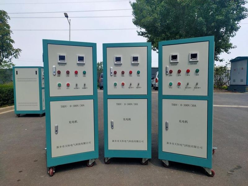
  In early summer, everything is flourishing. During this vibrant season, Tianheng Electric successfully completed the production and delivery of a charging machine for a certain airport.  This charging machine is mainly used for the daily maintenance of ground vehicle batteries at the airport, meeting the safety production needs for charging lead-acid batteries used in vehicles and equipment belonging to the ground service department.  The intelligent charging and discharging equipment is specially designed for battery groups. It can perform maintenance and capacity calibration for lead-acid, nickel-cadmium, nickel-hydrogen, and lithium iron batteries used in DC power sources of substations (or power plants), railway locomotives, armored vehicles, tanks, vehicles, generator vehicles, and other applications. This enhances battery life and ensures the safe operation of DC power sources and equipment such as locomotives and vehicles.  Charging machines used in special environments require strict performance standards. Various departments of the company worked closely together, following standard procedures for production, inspection, debugging, and shipment to ensure timely delivery of orders.  Product quality delivery validates trustworthiness. Tianheng Electric serves customers with dedication, adhering to stringent delivery standards and providing full-process delivery services to safeguard customers' ongoing stable and safe production.
2023-05-25
Automatic Constant Current Charging and Discharging Units Successfully Delivered
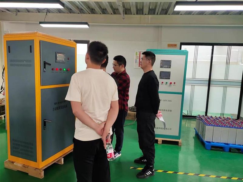
Recently, the automatic constant current charging and discharging units produced by our company for a locomotive depot were successfully delivered.Faced with lockdowns during the pandemic and the urgent need for delivery at the customer site, the company's employees worked overtime, reasonably arranged and scheduled production, and delivered this batch of automatic constant current charging and discharging units on time to meet customer needs.This automatic constant current charging and discharging unit consists of 16 units controlled via an upper-level system. It can be operated on the local screen, monitored and operated in real-time on the upper-level system, and can also upload data to the customer's system. Data is automatically generated into tables and can be printed or stored according to customer needs. The automatic constant current charging and discharging units produced by Tianheng Electric have been used for many years in railways, subways, and mines, with reliable quality and simple operation. They have also been successfully exported to multiple countries and have received high praise from users.The images below show the application site of the automatic constant current charging and discharging unit for the Egyptian subway project. Our technical personnel carefully communicated with the customer on-site, providing guidance to ensure the correct understanding and use of our products.
2022-11-30
1234 共48条 4页,到第 确定
186-3733-3097
189-0380-1549

关注微信